Sunday, 30 October 2016

II4033 - Digital Forensic Tugas Ujian Tengah Semester. (CW: No Rant Inside)

Problem Set 1 - http://old.honeynet.org/scans/scan24/

Skenario


Singkat cerita, Joe Jacobs, 28, ditangkap karena dugaan mengedarkan narkotika kepada anak - anak SMA. Joe Jacobs ditahan saat ia melancarkan aksinya di SMA Smith Hill. Polisi telah menyita barang bukti sebuah floppy disk untuk kasus tersebut. Disk tersebut telah dibuatkan image oleh polisi untuk dianalisis. Joe Jacobs telah menyerahkan jaminan sejumlah US$10.000,- agar dapat dibebaskan. Polisi harus dapat segera menganalisis barang bukti tersebut agar Jacobs dapat ditahan sebelum ia berhasil kabur dari kota.

Pertanyaan

Kasus tersebut membutuhkan sejumlah pertanyaan untuk dijawab agar dapat menghasilkan bukti yang tidak terbantahkan untuk menahan Joe Jacob. Pertanyaannya adalah:

  1. Siapa dan di mana alamat penyedia ganja untuk Jacobs?
  2. Adakah data penting di dalam berkas coverpage.jpg dan mengapa hal tersebut penting?
  3. Sebutkan nama - nama sekolah lain selain SMA Smith Hill (jika ada)
  4. Proses apa saja yang dilakukan tersangka kepada setiap berkas agar berkas tersebut sulit untuk diidentifikasi dan dianalisis?
  5. Proses apa saja yang dilakukan penyelidik (anda) dalam memeriksa setiap isi dari berkas?

Sumber Barang Bukti

image.zip MD5 = b676147f63923e1f428131d59b1d6a72 ( image.zip )

Kakas Untuk Pengerjaan

·       Autopsy (http://www.sleuthkit.org/autopsy/
·       The Sleuth Kit (http://www.sleuthkit.org/)
Binwalk (http://binwalk.org/)

Langkah Kerja

File pertama yang memiliki sejumlah petunjuk adalah file Jimmy Jungle.doc yang memiliki isi sbb:


isi dokumen Jimmy Jungle.doc

Jelas sekali dokumen tersebut memberikan identitas suplier ganja yang merupakan rekan dari Joe Jacob. Hal tersebut otomatis memberikan jawaban soal No. 1.
File selanjutnya yang memberikan petunjuk adalah scheduled visits.exe . File tersebut memiliki mismatch pada ekstensinya yang menyebabkan kesulitan dalam melakukan ektraksi. Jika file tersebut diekspor menggunakan autopsy dan kemudian di ekstrak, maka ektraktor akan mengeluarkan error “end not found”. Binwalk dapat mengektraksi file ini dengan sempurna, namun file ini ternyata dilindungi oleh kata sandi.


ekstensi mismatch pada file scheduled visits

File selanjutnya yang harus diperiksa adalah Cover Page.jpgc . File tersebut memiliki keanehan dalam informasi sektor dan ukuran filenya. Kedua hal tersebut tidak cocok. File tersebut menunjuk kepada sektor 451 saja, namun ukuran file tersebut adalah 15585 byte yang jika dicari jumlah sektor yang digunakan oleh file tersebut akan menghasilkan 31 sektor ((15585+511) div 512). Jumlah sektor tersebut secara kebetulan sama dengan rantai sektor sisa yang teralokasikan, yaitu 73-103. Pengecekan setiap sektor 103 akan menghasilkan informasi baru yaitu password file scheduled visits.zip yang sebelumnya.

isi sektor 103 jika dicek menggunakan autopsy

Kata sandi tersebut berfungsi pada file scheduled visits.zip . File tersebut berisikan file scheduled visists.xls yang berisikan nama – nama sekolah yang dikunjungi oleh Joe Jacob. Hal tersebut sekaligus menjawab pertanyaan nomor 3.


Nama - nama sekolah yang dikunjungi Joe Jacob

Berikut adalah jawaban no. 4:

  • Cover page.jpgc: mengganti informasi sektor tempat file disimpan
  • Jimmy Jungle.doc: menghapus file
  • Scheduled Visits.exe: mengganti ekstensi file

dan jawaban no. 5 telah dijabarkan sejalan dengan penjelasan langkah kerja.


Problem Set 2 - http://pivotproject.org/challenges/forensic-image-extraction

Skenario

Pembelajaran dalam melakukan pengekstrakan berkas dengan menggunakan FTK Imager.

Pertanyaan


  1. Terdapat kombinasi di dalam berkas 001 - apa dan untuk apa kombinasi tersbut?
  2. Kapan waktu dan tanggal pertemuan? Kejahatan apakah yang dilakukan?
  3. Apa senjata yang digunakan pembunuh?
  4. Siapakah koban pembunuhan?


Sumber Barang Bukti

FlashOne.001FlashTwo.001


Kakas Untuk Pengerjaan

FTK Imager (http://accessdata.com/product-download/digital-forensics/ftk-imager-version-3.4.2)


Langkah Kerja

Soal ini dikerjakan hanya dengan menggunakan satu tool yaitu FTK Imager. Proses pengerjaan dilakukan dengan memeriksa setiap file di dalam image satu demi satu. Petunjuk pertama yang ditemukan adalah fungsi kombinasi. Kombinasi tersbut digunakan untuk membuka brankas. Informasi tersebut didapatkan di dalam file todo.txt.


isi file todo.txt

Petunjuk selanjutnya ditemukan di dalam file 2.jpg dengan menggunakan text editor. Kombinasi brankas ditemukan di dalam file tersebut. Kedua file tersebut sekaligus enjawab pertanyaan nomor 1.


isi file 2.jpg dilihat dengan text editor
File selanjutnya yang mengandung informasi adalah file journal.doc dan Bank Location.doc .  Berikut adalah isi dari file tersebut.


isi dari journal.doc


isi dari Bank Location.doc
Kedua file tersebut sekaligus menjawab pertanyaan nomor 2.
File selanjutnya yang memiliki informasi adalah file !.jpg . File tersebut mengandung informasi tentang siapa korban pembunuhan. File ini menjawab pertanyaan nomor 4. Nama korban adalah Dolly Parton, seorang penyanyi berkewarganegaraan Amerika Serikat. Berikut merupakan file !.jpg .


Dolly Parton, korban pembunuhan

File selanjutnya yang memiliki informasi adalah file 4.jpg . File tersebut memiliki informasi mengenai senjata yang digunakan untuk melakukan pembunuhan. File tersebut sekaligus menjawab pertanyaan nomor 3. Berikut adalah isi file 4.jpg .


senjata pembunuhan Dolly Parton. Kaleng Hairspray yang mencurigakan

Problem Set 3 - http://pivotproject.org/challenges/digital-forensics-challenge

Skenario - TBA
Pertanyaan - TBA
Sumber Barang Bukti - TBA
Kakas Untuk Pengerjaan - TBA
Langkah Kerja - TBA

Thursday, 28 April 2016

[HCII] Thingspeak & get command error, the not-so-detail details.

Alright, i will talk about the localhost one first. First of all, the decision of using localhost as the server was triggered by our desperation with the way thingspeak server did its job. We thought that the server was really busy so that our request can't be processed. Once we decided to use localhost, Harits decided to tinker a bit using it, and he finally found the way to actually make it work. Using a slightly different syntax of GET HTTP command, he achieved the result as told in the previous post. Here is the syntax:


The actual source code could be viewed here.

And then, the thingspeak one. Since Harits found that the syntax was slightly different, he decided to tweak it a little to use it to connect to the thingspeak. The result could be viewed in the previous post. Anyway, here is the picture about the changes in the source code:

before:

after:


an obvious error lol. The syntax was wrong. I guess we got the wrong reference of source code on the first pircture lol. Sorry for our incompetence.

[HCII] Another Update, Deal with it. CW: Rant Inside

Yes, it's about another update on my Human-Computer Interaction Interface final project, deal with it.

At least, we're over with ESP programming by using localhost instead of thingspeak as a server. Harits has done some wonder work in this as i don't know how he made it to be honest (gotta check the source code and the server later). Apparently, thingspeak is so busy processing other users requests so that ours got neglected and resulted in "server busy blah blah" error. I don't know how and frankly don't really care why, but at least we have put a problem to its rest.


Yeah, never trust thingspeak.

Oh, and here's some proof.


So this week was mainly about setting up the OV7670 camera module, or finding on how to stream a video from an arduino-connected camera. We found some library at www.arducam.com . You might want to check it for yourself in http://www.arducam.com/download/ . The problem is..... it sets and tweaks the camera in a low-level fashion, and it is kinda hard to learn it, and the functions/procedures in the library isn't really well defined (at least in english). Am i joking? No i am not, check it by yourself (of course i would really appreciate your help if you understand something).

As we were having a hard time learning it, we found another solution by using an android application named IP WebCam that turns your smartphone camera into network camera. Harits found a YouTube tutorial and he set his cellphone just as the video instructed and somehow it worked. Anyway, here is the video:


So, what's next?


IP WebCam might work, but we still have to figure out how to combine it with the webpage and the arduino, of course if we've decided to use it. It's not final yet. We still could make the OV7670 work but the possibility is lower than just using the IP WebCam.


Gotta run, thanks for reading the post. I'll see you when i see the fit time.


EDIT (28/04/16 10.40 PM):

Harits somehow found a way to send data to thingspeak. Turns out because of the Get HTTP protocol error that made the data transfer to thingspeak failed. I still have to read the source code first so i can tell you what was wrong and how he overcame the problem. I will update it once i get the source code. Anyway, Here's some proof:


Kudos to Harits, Undeniably MVP of this week. And kudos to everyone too, you all have been a great help.

Thursday, 21 April 2016

[HCII] Yet another update of final project

Yet another update.

This week was all about thingspeak. I don'treally have the idea why but it sucks. We can't really put something on it, but we still tried to do it, at least until today.

Oh, and yeah, we did make an automation of connecting to an access point. Should be easy, but at one time, my friend mis-assembled a part and it became like this:


yes, he assembled it in an inverse manner of what it should be. I reckon it must be the RX and TX pin (we didn't work in one place, only via instant messaging app). And at least, after the circuit is re-assembled (in a right manner), we got a response like this:


I don't really know why Harits referred me as "some friends" as i actually am his teammate, but from what i saw from the code at that time, we missed a function to configure the ESP and that is the configuration of the transmission method as it should be set to unicast. By source code function, it should be "AT+CIPMUX=1". And then, the result became this:


And you know what? That "Send OK" was just a lie as the thingspeak didn't receive anything to be shown in graph. We look for the problems again and i, once again hypothesized  from the source code, that the size allocation of the data that would be sent was not configured well. So Harits made a change to the source code by adding these four lines of code:


and the result is:


I would really use swearing words right here if only Mr. Soni wouldn't read my post. (No no no sir, i'm not suggesting you to not reading my post. I still need the mark to pass the class).

So, moral value of the story: Never trust Thingspeak, or IoT, or me, or my friends. (No no no i trust you guys from all of my life, ok that's exaggerating, but i trust you all, or maybe not. Banter.)

Oh i almost forgot, Harits had actually bought the camera. Its name is OV7670 Camera Module (yass another new toy to tinker with..... hold on, i only have a week left, poor me). You can see the specifications here:

http://www.elecfreaks.com/store/ov7670-camera-module-p-705.html

or you might just want to google it yourselves. Fine, whatever. :v

So Harits found a circuit scheme of how to connect this camera module to the arduino. He said he got it from a friend. Too bad he didn't understand how to assemble it. Welp, at least you tried :v

Here is the schemantic:


Yeah, it looks complex :v

Moral story of the final project so far:
  • Never trust Thingspeak
  • IoT takes much the hassle
  • WiFi module might could help you, but it is more likely slow you down if you had no idea about it. It might kill you if you choked on it :v
  • Configuring ESP is a pain itself
  • It may took an uber-hipster-expert-but-not-so-expert to assemble a Camera Module circuit schemantic, or maybe not :v
  • Never trust thingspeak (yeah i said it twice, it is intentional :v)
  • You could ask for your friends help, but that might not bring much help (i said friends, not teammate). :v


Oh almost forgot, here is the link of the source code so far:

https://github.com/harits-adhi/IMKA/blob/master/tesHC.ino

Thursday, 14 April 2016

[HCII] yet another update

It has been two weeks, eh? Truth to be told, i'm getting bored of examining and testing these things so called wifi modules and shields. Got ourselves a WiFi Shield, only not really that applicable. You know, the DFRobot WiFi Shield v3 TEL0079, that doesn't come with any manual or instruction, even it doesn't support the official arduino WiFi library (correct me if i'm wrong, really, i need many corrections right now). The only thing that helps by using this shield is that the configuration is much easier, as it came with a settings webpage (10.10.100.254) and you could set it up like a normal router (finally i'm happy to see something normal).

DFRobot WiFi Shield V3 RPSMA TEL0079


What about the ESP? That is the one that made me bored for these two weeks of tinkering. You know, since i am not really that interested in programming a web or doing something like manual http request, it doesn't attract me so much than just assembling a circuit and program the arduino "normally", let alone making a web page. IoT and i never really get going anyway.

So, what's the deal? As far as i see, we got two options right now: push the shield hard or carry on with the ESP.

Oh, yeah, here is the bonus: High-level design for our Baby Monitor project.
Use Case Diagram of Baby Monitor
Activity Diagram of Baby Monitor

DFRobot WiFi Shield V3 official page: http://www.dfrobot.com/index.php?route=product/product&product_id=1101#.VxBB-0dnfIU

PS: I actually am really grateful that Mr. Soni lent us the shield, shame that it doesn't really work out. I'm sorry if i wrote something unpleasant, but that is what actually happened.

Thursday, 31 March 2016

[HCII] yet another final project update

No, i won't give any April fool joke.

April Fool.

That's the joke.

OK, Back to the money game.

Once again, the project is not done yet. This time, we tried to get the arduino to send an email to a specified email address in the source code. The contain of the email is also specified. Sadly, it is no walk in a park.

The thing that we had to get over with is the firmware version of the ESP. Some source code we found on the internet will only work with a specified version of the firmware. So,we spend entire yesterday to upgrade the firmware. Too bad, updating the firmware itself is too much hassle and has its own difficulties, Like, i have to press down the reset button in the ESP while uploading the new firmware into it and I didn't see any button on it. And as far as i know, the ESP we bought didn't come with any manual. Then we tried to search the datasheet over the internet, sadly it doesn't adequately bring a help. So much hassle to find a button.

And so, here we are, empty handed again. We'll still working on this anyway. Stay tuned for the updates.

The link of the sources will be added. For you who want to know the source, please remind me to add it.

Thursday, 24 March 2016

[HCII] Final Project Update 25-03-16

Am not going to rant. This is what actually happened with our project so far.


The Basic Components of the Baby Monitor project as taken from Han's Blog

As you can see in the previous post, we are trying to make a baby monitor which would send a notification to user's device if something happened. By those simple definition, you can see there will be data transfer process in the project. Personally, I think that this process will be one of the hardest to be done, and I guess all of our team member feel the same. So we tried to cover this one first.

For this part, we decided to use our old ESP8266 as we should be familiar to use it already. So, the components and the circuit design should be the same as the ones in my previous ESP8266 post. Just a reminder that the circuit design is not final as we still haven't add a microphone and a camera to it.
Circuit Design

The only thing we find missing is how does an ESP8266 transfer a data to other device? And what device should it be? For those question, we found something named Blynk. Blynk is an application for smartphone (android and iOS) that is designed to connect a Raspberry Pi, Arduino, ESP8266 and many other hardware to a smartphone. To be honest, I am not really sure that this is what we are looking for since its documents doesn't say anything about image transfer, but i still think it would be worthy enough to try.

And so, the team members, except me, decided to try Blynk on Tuesday (it's 22 March if your calendar has been teared to pieces). Too bad I wasn't there to try it due to an appointment with a lecturer's assistant. And as I came back from the appointment to see the progress of those three doing, they still haven't find a way around to make it work. After that, we decided to end our try because of other assignment and other's hectic schedule. 

We could have get it covered by this week, sadly, we did not. For that i would like to offer my apology to you if you're not satisfied with our work on behalf of my team. Next time, we will come with better time management. And my apologise to every member of my team if i'm not being useful enough for this week. 

We will get this one covered. Stay tuned.

And tonight, we ride.

Thursday, 17 March 2016

[HCII] Final Project Idea: an-unnamed-yet Baby Monitor

I know, i don't really have time for a pointless rant, but let me rant please!

Cursed Management Project class is making me crazy. You know i didn't sign up for this, and they don't pay me enough to do this. Curse it.

I will not apologise this time, sorry but no sorry.

Down to the real business.

This time the class was told to make something based on arduino (or any other microcontroller board) for the final project. And yes, I have to post something to my not-so-beautiful blog about it. The point is, this post will be about our idea for our final project in Human Computer Interaction and Interface course.


Idea

The idea is actually not mine, it's Han's. I don't know where the <censored> she got her idea from, but it could definitely work. The idea is to make a baby monitor so that when the baby cries the system will send something like a notification or an alarm to the parent via network. A responsible parent would rush to their baby to check their condition if a notification has been sent to them (if you're not, curse you).

I really hope the babies will start singing some death metal song to annoy their parent (or maybe give their parents a heart attack).

There will be a camera that records the babies image and will send the babies picture to their parents when the parents feel like it to a device of their choices (actually, it's not defined yet which device the picture will be sent to). If the babies go out of the sight of the camera, then a notification will be sent to their parents so that the parent will see their babies sing a black metal song.

Hail Satan... or the Vikings.


Expected Components

  • Arduino Uno
  • a camera
  • buzzer
  • microphone
  • Wireless Network Module (High chance that the ESP8266 will be used)
  • Jumper Wires
  • Breadboard
  • LCD to simulate the notification

Circuit Design

TBA.


oh, and yeah, a bonus video for you. 


Thank you for reading.

Thursday, 3 March 2016

Second Project: Arduino Calculator, or a Calcu-later (at least according to Han)


I know, I had to make another post. Our team have just finished another project, and yet somehow we've finished it on time (again) given two (or maybe three) weeks time by our lecturer.


My honest apologise to you regarding the rant above. Let us proceed to the business.


This time, our lecturer made us to build a calculator based on Arduino. The calculator itself contains only by basic functions of calculator (not the scientific ones), so there will be only four functions and those are addition, subtraction, multiplication, and division.


Idea

The project is about an arduino calculator. It uses Arduino, 4x4 keypad, and LCD (Should be obvious what we are going to make with those components, but i will still explain it to you). The keypad will bring the input to the arduino from user's input and display it to the LCD, then the board will calculate the mathematical instruction and will also display the result to the LCD.


Components


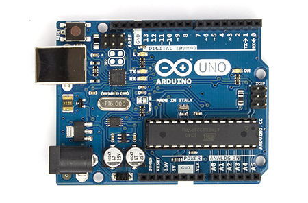
  • Arduino Uno
Arduino Uno

  • Jumper Wires
Jumper Wires
  • 1 piece of Keypad 4x4
Keypad 4x4

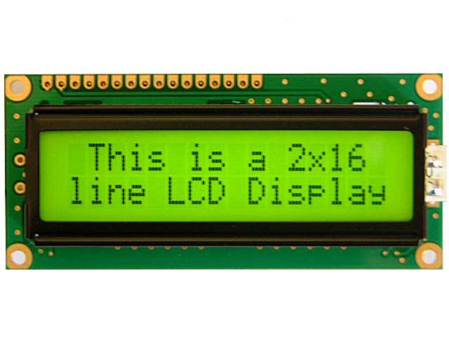
  • 1 piece of LCD 16x2
LCD 16x2
  • 1 piece of Variable Resistor or Potentiometer
Variable Resistors


  • 1 piece of 220 Ohm Resistor

220 Ohm Resistor

Circuit Scheme


Source Code

The source code could be viewed here.
The Keypad Library could be downloaded here.
The LCD library comes with Arduino IDE.

Problems Faced

Dealing with a LCD is no joke. Simple wiring mistake could cost you a time of life. From our experiences, we have succeeded in assembling the circuit, but when we run it with the source code, the LCD won't display anything beside some weird boxes. We try to sort out the keypad first, turns out that the keypad was not the problem. Then we try to sort out the LCD, and yes, reading a LCD datasheet is one troublesome activity, but somewhat we went through it by not caring much of the details. At first, we thought that the pin assignment was the problem, turns out it was not. After all the hassle, we found that the way that the wires doing their job is the problem. We used an un-soldered LCD at that time, so we decided to use the one which is soldered with a male header (we borrowed it from a friend). Finally, the trick solves the problem.

Another problem we had dealt with is the key assigning of the keypad. The '1' key was replaced by '7', '2' was replaced by '8', and '3' was replaced by '9'. The solution is to alter the source code a little, and now the keypad works like charm.

Photos and Videos


The LCD is displaying the user's input and the mathematical result.


References


Special Thanks

Vathsav Harikishnan for his tutorial.
Aldo Aditiya Nugroho for lending us his soldered LCD.

First try: ESP8266 Wireless Network Module

Yeah, I'm back. Surprised yet?

It has been several weeks since the last time I posted about our first project in Human-Computer Interaction Interface course. I'm still waiting for the release of the PC version of the newest installment on Need For Speed, and I found a new joy in playing Project Cars, and yes, Rio Haryanto is now officially a Formula One driver (am still waiting for my time though :v). Just how fast the time could pass by? :v

Ah, my apologize, enough of the pointless rant. Let us carry on to the real business, shall we?

This time, I don't know if it could still be called as a project, but our lecturer made us try the Wireless Network Module named ESP8266. The Module itself costs us Rp75.000,- (about $5.5 with current exchange rate). The ESP8266 WiFi Module itself is a self contained SOC with integrated TCP/IP protocol stack that can give any microcontroller access to your WiFi network. So, it's basically like the network card that a microcontroller could use (I hope I don't give you a false analogy).


Idea


Should be obvious enough. :v


Components


The Components used in this not-so-called-project are:

  • Arduino Uno

Arduino Uno

  • ESP8266 WiFi Module
Esp8266 Module

  • Breadboard
Breadboard

  • Male-Female Jumper Wires
Male-Female Jumper Wires

  • Male-Male Jumper Wires
Male-Male Jumper Wires

Circuit Scheme


Circuit Scheme

Source Code


No need for it. The Module has a built-in commands. The Module's quick start guide that is attached in the references section will guide you (Captain Obvious strikes back baby!) to test this module's capability.

Problems Faced


I don't really think that there is anything I could consider as a problem, except that one time when we need a Male-Female jumper wires to carry on this not-so-called-project. :v


Photos and Videos


References: