I know, I had to make another post. Our team have just finished another project, and yet somehow we've finished it on time (again) given two (or maybe three) weeks time by our lecturer.
My honest apologise to you regarding the rant above. Let us proceed to the business.
This time, our lecturer made us to build a calculator based on Arduino. The calculator itself contains only by basic functions of calculator (not the scientific ones), so there will be only four functions and those are addition, subtraction, multiplication, and division.
Idea
The project is about an arduino calculator. It uses Arduino, 4x4 keypad, and LCD (Should be obvious what we are going to make with those components, but i will still explain it to you). The keypad will bring the input to the arduino from user's input and display it to the LCD, then the board will calculate the mathematical instruction and will also display the result to the LCD.
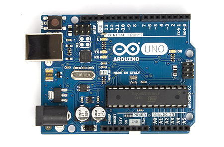
- Arduino Uno
Arduino Uno
- Jumper Wires
Jumper Wires
- 1 piece of Keypad 4x4
Keypad 4x4
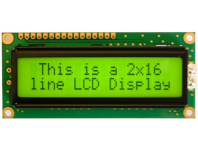
- 1 piece of LCD 16x2
LCD 16x2
- 1 piece of Variable Resistor or Potentiometer
Variable Resistors
- 1 piece of 220 Ohm Resistor
220 Ohm Resistor
Circuit Scheme
Circuit Scheme. Source: www.vathsav.com/img/arduino_calculator/sketch.png
Source Code
The source code could be viewed here.
The Keypad Library could be downloaded here.
The LCD library comes with Arduino IDE.
Problems Faced
Dealing with a LCD is no joke. Simple wiring mistake could cost you a time of life. From our experiences, we have succeeded in assembling the circuit, but when we run it with the source code, the LCD won't display anything beside some weird boxes. We try to sort out the keypad first, turns out that the keypad was not the problem. Then we try to sort out the LCD, and yes, reading a LCD datasheet is one troublesome activity, but somewhat we went through it by not caring much of the details. At first, we thought that the pin assignment was the problem, turns out it was not. After all the hassle, we found that the way that the wires doing their job is the problem. We used an un-soldered LCD at that time, so we decided to use the one which is soldered with a male header (we borrowed it from a friend). Finally, the trick solves the problem.
Another problem we had dealt with is the key assigning of the keypad. The '1' key was replaced by '7', '2' was replaced by '8', and '3' was replaced by '9'. The solution is to alter the source code a little, and now the keypad works like charm.
Photos and Videos
The LCD is displaying the user's input and the mathematical result.
References
Special Thanks
Vathsav Harikishnan for his tutorial.
Aldo Aditiya Nugroho for lending us his soldered LCD.


No comments:
Post a Comment